Introduction
An inverter rarely fails because of one isolated component. In real industrial and energy-storage projects, premature failures are usually the result of repeated thermal stress, electrical overstress, poor cooling, environmental contamination, or insufficient maintenance.
The important question is therefore not simply “How long can this inverter operate?” but rather “What operating conditions are consuming its reliability margin?”
Field reliability studies consistently identify power semiconductors and capacitors as critical components, while thermal cycling is a major contributor to long-term degradation.
1. Thermal Stress and Temperature Cycling
High temperature is not the only problem. Repeated temperature changes can be even more damaging.
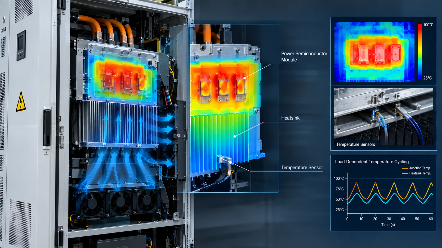
IGBTs and other power semiconductor modules repeatedly heat and cool during changing loads. This creates mechanical stress between materials with different thermal expansion characteristics. Over time, bond wires, solder layers and interconnections can degrade.
Engineering check:
Do not only record the maximum temperature. Monitor junction/case temperature, temperature rise, load profile and thermal cycling frequency.
2. DC-Link Capacitor Aging
DC-link capacitors are another common reliability bottleneck.
Ripple current generates internal heating, while elevated temperature accelerates capacitor aging. A capacitor can therefore appear electrically normal during commissioning but gradually lose capacitance or develop increased ESR after long-term operation.
Engineering check:
During preventive maintenance, compare capacitance, ESR, ripple-current conditions and operating temperature rather than waiting for a capacitor failure.
3. Electrical Overstress
Short-duration electrical events can cause long-term damage.
DC-bus overvoltage, grid transients, excessive current, short circuits and abnormal switching conditions can overstress IGBTs, MOSFETs, capacitors and gate-drive circuits. Some failures occur immediately; others leave degradation that becomes visible months later.
Engineering check:
When investigating repeated inverter trips, examine the event waveform, not only the fault code.
4. Cooling System and Installation Conditions
A correctly rated inverter can still have a short service life if the thermal design of the cabinet is poor.
Blocked air passages, dust accumulation, fan degradation, poor cabinet ventilation and deteriorated thermal-interface materials can gradually reduce thermal margin. In practice, an inverter that operates close to its thermal limit has less tolerance for overloads and abnormal events.
Engineering check:
Inspect airflow direction, fan condition, heatsink contamination, cabinet temperature and thermal-interface condition during maintenance.
5. Mission Profile and Preventive Maintenance
Nameplate power alone does not determine inverter lifetime.
Two identical inverters can experience very different aging rates because one operates under relatively stable loading while the other experiences frequent startup, shutdown, overload and rapid power changes.
A useful maintenance strategy should therefore combine load profile + temperature history + alarm history + component condition.
Reliability Factor | Typical Failure Risk | Recommended Check |
Thermal cycling | IGBT/module degradation | Temperature profile |
High temperature | Capacitor aging | Cabinet & component temperature |
Electrical overstress | Semiconductor failure | DC-bus/grid waveform |
Poor cooling | Thermal shutdown/aging | Fans, airflow, heatsink |
Harsh mission profile | Accelerated aging | Load & operating history |
Note: These are engineering screening categories rather than universal failure-rate percentages. Actual lifetime depends on topology, components, mission profile and installation conditions.
Project Experience: “The Inverter Passed the Test—So Why Did It Fail in the Field?”
A common engineering mistake is to conclude that an inverter is reliable because it passed a short laboratory test.
In one typical integration scenario, the inverter performed normally during factory testing. After installation, however, repeated high-load operation caused thermal alarms and intermittent trips.
The root cause was not simply the inverter's rated power. The integrated system had higher cabinet temperature, restricted airflow and a more aggressive load profile than the laboratory test condition.
This is why reliability should be evaluated at the system level, not only at the component or nameplate level.
Need a customized bidirectional isolated topology?
Submit your electrical parameters to the IDEALPLUSING senior engineering team for a free technical evaluation. We can help assess topology selection, voltage/current requirements, isolation architecture and application conditions before the design moves into the next stage.
Conclusion
Inverter lifetime is determined by more than component quality.
For engineers, the most practical approach is to control the five major factors: thermal stress, capacitor aging, electrical overstress, cooling conditions and mission profile.
The best reliability strategy is not simply to select a higher-rated inverter. It is to reduce unnecessary stress, maintain thermal margin and continuously monitor degradation indicators before they become failures.