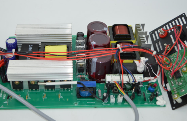
A pure sine wave inverter is a power conversion device that converts DC power into pure sinusoidal AC power. It plays an important role in many applications, such as solar and wind power generation systems, UPS uninterruptible power supplies, electric vehicle chargers, etc. This article will introduce the working principle of a pure sine wave inverter in detail.
Working Principle of Pure Sine Wave Inverter
The working principle of a pure sine wave inverter is realized through a series of electronic components and control circuits. First, the input of the inverter is DC power, usually a battery voltage of 12V, 24V or 48V. The output of the inverter is AC power, usually an AC voltage of 220V or 110V, with a frequency of 50Hz or 60Hz. The basic components of the inverter include DC input, AC output, power switch, control circuit and filter circuit.
The DC input is the input interface of the inverter, which is generally connected to the positive and negative poles of the battery. The AC output is the output interface of the inverter, which is generally a socket that provides 220V or 110V AC power.
The power switch is the core component of the inverter, which is responsible for converting DC power into AC power. The power switch usually uses devices such as MOSFET, IGBT or high-power diode. The control circuit ensures that the voltage and frequency output by the inverter meet the requirements by controlling the power switch.
The filter circuit is used to smooth the AC power output by the inverter and remove the harmonic components. The filter circuit is usually composed of inductors and capacitors. Their function is to make the voltage output by the inverter as close to a pure sine wave as possible through filtering and harmonic suppression.

The working process of a pure sine wave inverter
Input DC power conversion
The inverter first converts the input DC power into AC power. This step requires the control circuit to control the conduction and cutoff of the power switch so that the DC power of the battery can be output through the power switch.
AC power output
The AC power output by the inverter becomes smoother and more stable after being processed by the filter circuit. The filter circuit converts the square wave voltage output by the inverter into an AC voltage as close to a pure sine wave as possible through a combination of inductors and capacitors.
Output voltage control
The inverter needs to control the output voltage according to demand. Usually, the output voltage is adjusted by the control circuit by controlling the switching frequency and duty cycle of the power switch.
Output frequency control
The output frequency of the inverter is usually fixed, generally 50Hz or 60Hz, matching the national or regional power grid standards. The control circuit can ensure that the frequency of the inverter output is consistent with the required frequency through precise timing control.
In short, a pure sine wave inverter is a device that converts direct current into pure sinusoidal alternating current. It converts the input direct current into output alternating current through the coordinated work of components such as power switches, control circuits, and filter circuits, and provides pure sinusoidal alternating current energy that meets the load requirements by strictly controlling the output voltage and frequency.


