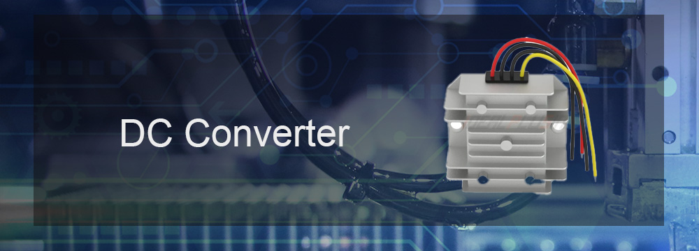
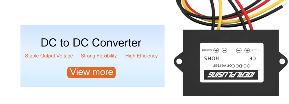
Buck Converter and Boost Converter are both common DC-DC converters used to convert DC voltage to different voltage levels. Buck converter steps down the input voltage to below the output voltage, while boost converter steps up the input voltage to above the output voltage.
What is a boost converter?
A boost converter is a DC/DC switching power supply that steps up an unregulated DC input voltage to achieve a regulated high output voltage. Similar to a buck converter, a boost converter relies on an inductor, diode, capacitor, and switch tube to regulate the output voltage, but they are configured differently. The simplified circuit diagram below shows the current path during the switching of a boost converter.
In a boost converter, the output voltage varies according to the ratio of the conducting switches of the PWM signal, equal to or greater than the input voltage. Due to power savings, a boost converter that provides three times the input voltage can only provide one-third of the current. However, boost converters are very common in battery-powered devices, such as a set of 3V battery voltage to power a 5V circuit.
How a boost converter works:
The basic principle of a boost converter is to generate the required boost voltage at the output by periodically switching the power input voltage. A boost converter mainly consists of a power switch, an inductor, and a capacitor.
1. Channel closed state: When the power switch is turned off, the energy storage current in the inductor is applied to the capacitor, and the output voltage begins to rise. The function of the inductor is to store energy, and the current remains constant.
2. Channel open state: When the power switch is turned on, the energy stored in the capacitor is transferred to the output end, and the voltage begins to drop.
In this state, the inductor and capacitor also form an oscillation loop to keep the output voltage stable.
By adjusting the duty cycle and duty cycle of the switch, the output voltage can be controlled. The higher the switching frequency, the smaller the ripple of the output voltage, but the loss of the switching device will also increase.
What is a buck-boost converter?
A buck-boost converter can provide a stable DC voltage output, whether the input voltage is higher or lower than the output voltage. The buck-boost converter circuit combines elements of the buck converter and the boost converter, but their size is usually larger than both. The simplified circuit diagram below shows the common current path during the switching of the buck-boost converter.
You may find that the voltage polarity of the output in the circuit diagram is opposite to the input voltage, which complicates the design. Buck-boost converters also require more expensive components because they have to withstand high voltages at the highest input voltage and large currents at the lowest input voltage.
But the buck-boost converter is well suited for a variety of applications, the most common of which is high-power LED lighting, such as a lead-acid battery providing a nominal 9-14V voltage for a 12V LED constant load.
Working principle of buck converter:
The basic principle of the buck converter is to generate the required step-down voltage at the output by periodically switching the power input voltage. The buck converter mainly consists of a power switch (usually a field effect transistor or a bipolar transistor), an inductor and a capacitor.
1. Channel closed state: When the power switch is turned off, the input voltage is applied to the inductor, and the charge on the capacitor begins to release. The role of the inductor is to store energy, and the current remains unchanged.
2. Channel open state: When the power switch is turned on, the energy stored in the inductor is transferred to the capacitor, and the output voltage begins to rise. In this state, the inductor and capacitor form an oscillation loop to keep the output voltage stable.
The output voltage can be controlled by adjusting the duty cycle and duty cycle of the switch. The higher the switching frequency, the smaller the ripple of the output voltage, but the loss of the switching device will also increase.
Summary: Buck converter and boost converter achieve voltage conversion by switching the input voltage periodically. Buck converter reduces the input voltage to the desired output voltage by controlling the duty cycle and duty cycle of the switch. Boost converter increases the input voltage to the desired output voltage. These converters are widely used in various electronic devices, such as power adapters, mobile phone chargers, etc.
IDEALPLUSING: Power Expert
IDEALPLUSING,focus on the research and development, sales and service of DC to DC power supply module,AC to DC rectifier module,
DC to A C inverter, AC power supply, DC power supply, LED power supply, charger,rectifier system and other fields,to provide
personalized, efficient, reliable and cost-effective power supply solutions for all industries.
It will not cost you one cent when you ask us anything, but it may be a chance for both of us!
Our dedicated team endeavors to respond within one hour.
Thank you for considering our services.


