It is not difficult to design an adjustable DC power supply, but it is difficult to do it accurately. Once you really get started, you can use discrete structures to easily gain experience and design step by step. Today, I will teach you how to design an adjustable DC power supply step by step.
1. What is an adjustable DC power supply
An electronic instrument that converts the power of the power grid into a special form of high-voltage power supply
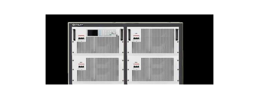
An adjustable DC power supply is an electronic instrument that converts the power of the power grid into a special form of high-voltage power supply. The adjustable DC power supply can be divided into positive and negative polarities according to the output voltage polarity.
2. Working principle and application of adjustable DC power supply
Adjustable DC regulated power supply has been widely used in various industries and also in the agricultural field, such as electrostatic dust removal in agricultural environment, electrostatic spray insecticide, electrostatic spraying and wrapping of agricultural materials, electrostatic flocking in agricultural product processing, research on electrostatic effects of agricultural organisms, electrostatic sterilization, electrostatic treatment of agricultural seeds, etc.
With the continuous development and progress of agricultural science and technology, the demand for high-voltage electrostatic power supplies in agricultural scientific research and agricultural engineering application practice has increased year by year, and many new requirements have been put forward for its accuracy, performance, specifications, varieties, types, volume, intelligent operation, etc. The existing high-voltage DC power supply can no longer meet many needs in the agricultural field. Research and development of a variety of new high-voltage DC regulated power supplies suitable for the requirements of the agricultural field has become an objective demand, and its social and economic benefits are relatively significant, and the market prospects are relatively bright.
3. Adjustable DC design
The first step in designing an adjustable DC power supply is to check the specifications. Today, I will briefly discuss the design ideas for designing a traditional isolated adjustable DC power supply with a wide input range.

3.1 First determine the performance, then choose the appropriate topology according to your specific needs
This multi-select flyback with an adjustable DC power supply can basically meet your requirements. Choose a more empirical formula here. If you need some analysis, you can discuss it.
3.2 Select PWM IC and MOS that match the rough design of the equivalent circuit
After deciding on the design with the flyback topology, you need to select PWM IC and MOS that match the preliminary schematic design (sch). You can decide for yourself whether to use it separately or in an integrated manner. Split the internal calculation.
Discrete: The advantage of separating PWM-IC and MOS is that the power can be adjusted freely. However, the disadvantage is that the design and debugging cycle is long (from a design point of view). Integrated: PWM IC and MOS are integrated in one. This package saves developers a lot of calculation and debugging steps, so it is suitable for new environments and rapid development.
3.3 Create a schematic
After confirming the selected chip, start creating a circuit diagram (sch).
It is a good idea to check the appropriate datasheet before designing to see simple parameters. Whether you choose PI integration or discrete options such as 384x or OBLD, you need to search the datasheet. The datasheet usually comes with a simple circuit diagram that forms the basis of the design.
3.4 Determine the appropriate parameters
After the schematic is ready, you need to determine the appropriate parameters for the next step of PCBLayout. Of course, different companies have different processes. You need to follow the appropriate process and develop good design habits. This step can include pre-evaluation, general confirmation, etc., and calculations can be performed after approval is completed.

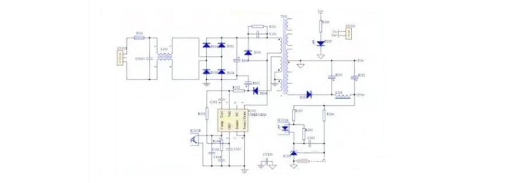
Circuit diagram of adjustable DC power supply
3.5 Determine the switching frequency and select the core to determine the transformer
The frequency of the chip can be adjusted by external RC, and the operating frequency corresponds to the switching frequency. This peripheral function helps to improve the design of the adjustable DC power supply, and an external synchronization function can also be used.
For a typical AC2DC converter, the operating frequency must be set to no more than 100 kHz. This is mainly because the frequency of the adjustable DC power supply is too high to improve system stability and EMC passability. If the frequency is too high, the corresponding di/dtdv/dt will increase. In addition to the PI132kHz operating frequency, you can also use other chips to summarize your experience.
The choice of the core is based on the switching frequency and power, which is a more empirical choice. Of course, in order to make calculations, you need to obtain more core magnetic parameters, such as magnetic materials, Curie temperature, frequency characteristics, etc. This must be done slowly.
3.6 Designing a transformer for calculation
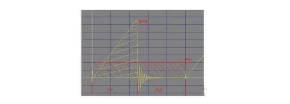
Select the known parameters of the core according to the input/output and switching frequency, and set parameters such as efficiency, maximum duty cycle, and magnetic induction intensity change at the same time. Then you can proceed to the next calculation step to find the power, average, peak voltage and current. Number of turns and inductance. The peak current entered here is about four times the average input current. This is a kind of experience. It can also be derived from the figure below.

The relationship between peak current and average current
By determining the number of turns of the enameled wire without any complicated calculations, you can directly check it.
The wire diameter corresponds to the conventional resistance and is a fixed value. Pay attention to some commonly used fixed value wire diameters. Since the primary current here is relatively small, φ0.25 can be used directly. Auxiliary winding φ0.25. The main output winding is φ0.4 or 0.53 strands, so you don’t have to choose a thicker winding. Otherwise, the hardness of the enameled wire will make it difficult for the operator to wind.
After many steps of this "calculation", return to the calculation to display the area of the converter window. I personally think that the return confirmation is redundant. If the winding is insufficient, the test transformer factory will also provide feedback, and if it passes the test, it may not necessarily pass. After all, because you are familiar with the actual packaging process, there is still a lot of work to do for sparseness.
The next step is to determine the size of the input and output capacitors. Then you can create a layout and layout.
3.7 Calculation of input and output electrolytic capacitors
Here, according to the input power and output current calculated in the previous step, determine the final specifications of the electrolytic capacitor, and select the frequency and impedance according to the application environment. The higher the theoretical value of the capacitor Cin, the better for the next stage, but there is no cost limit. Please choose a large capacity.
Basically, the components on the circuit board that need a certain shape are complete, that is, the packaging of the circuit board is complete. The next step is to define the device package using the previous circuit diagram (SCH).
3.8 Circuit board layout
The above are transformers, circuit diagrams, electrolytic capacitors, and other basically standard parts.
Generate a netlist with sch, define the edge of the card with a PCB file, and load the appropriate package library. You can directly import the netlist for layout. The board is relatively simple, so you can even do the layout right away. We recommend that you import the netlist. Design habits.
The focus of PCB layout is not the connection method, but the layout method. Generally, it is much easier to draw the board when it is arranged in order.
From the perspective of layout and layout:
1) The loop area formed by the RCD absorber and the transformer should be as small as possible. This can reduce the corresponding radiation and conduction.
2) The ground wire should be as short and wide as possible so that the corresponding zero level can ensure the stability of the reference. At the same time, VIPER53DIP is an important channel for DIP-8 chip heat dissipation.
3) If the change of di/dtdv/dt is relatively large, minimize the loop and widen the curve to reduce unnecessary inductance characteristics.
The corresponding figure is attached. A long time ago, many improvements were made to the N version. For reference, the board is still in production.
3.9. Determine some parameters
I calculated the transformer in the first few steps. Once the PCB layout is completed, the end of the transformer of the same name can be determined, the transformer can be fully defined and sent for calibration or self-winding.
3.10. Debugging process
In the previous part, the power supply has basically been designed and completed. The following is the debugging process of the welding board.
Simple debugging equipment required (required): voltage regulator, oscilloscope, multimeter, additional equipment: power meter, LCR bridge, electronic load
After welding the board, perform a static test. If you have an LCR bridge, you can test the transformer with the same name, inductance and different parameters before welding.
Static inspection: mainly depends on the presence of solder joints, solder joints, etc. After the static test, you can use a multimeter to test whether the input is short-circuited. The rest can be opened.
Making an adjustable DC power supply can not only meet the needs of different electronic experiments, but also help you deeply understand the working principle of the power supply circuit. By reasonably selecting transformers, rectifier filter circuits, voltage regulator modules and voltage regulating components, you can create a stable and reliable adjustable power supply.
Share our interesting knowledge and stories on social media


